Что нового?
Форум выживальщиков

Зарегистрируйте бесплатную учетную запись сегодня, чтобы стать участником нашего сообщества! После входа в систему вы сможете участвовать на этом сайте, добавляя свои собственные темы и сообщения, а также общаться с другими участниками.

SW-GSM CW (SGC) маяк - Программное обеспечение

EdGull

Выживальщик
Регистрация
22 Июл 2012
Сообщения
1,395
Поблагодарили
681
Город
Тольятти
Подключил к основной плате блютузину, на телефоне установил терминалку
Тестовый код, работает, светодиод моргает, телефон информацию с уарта отображает.

$prog &HFF , &HFF , &HD9 , &HFF ' generated. Take care that the chip supports all fuse bytes.
$regfile = "m2560def.dat"
$crystal = 16000000
$baud = 9600

Dim A As Byte
Config Portb.7 = Output : Led Alias Portb.7

Print "Start SGC-Beacon"

Do
Print A ; " " ; Chr(13);
Led = 1
Waitms 250
A = A + 1
Led = 0
Waitms 250
Loop

Завтра будем подключать бипер и будем пищать морзянку.
 
Последнее редактирование:
  • Like
Поблагодарили: V22Rus

EdGull

Выживальщик
Регистрация
22 Июл 2012
Сообщения
1,395
Поблагодарили
681
Город
Тольятти
Кстати для желающих приобщиться, отличный букварь по Bascom AVR Basic

http://decada.org.ru/project/lessons/bascom_avr/10/

Там же есть исходник CW-маяка
http://decada.org.ru/project/lessons/bascom_avr/15/sendmorse.bas

$regfile = "2313def.dat"
$crystal = 4000000

Dim Sendstring As String * 36
Dim Sendchar As String * 1
Dim Charcode As Byte
Dim Dataindex As Byte
Dim Charindex As Byte
Dim Nextcharindex As Byte
Dim Charstring As String * 12
Dim Stringlength As Byte
Dim Codelength As Byte
Dim Codeindex As Byte
Dim Codeelement As String * 1
Dim Concatindex As Byte

Soundpin Alias Pinb.0
Morsepin Alias Portb.0

'Set Speed and Dot, they determine the remaining constants
Const Speed = 12
Const Dot = 600 / Speed
Const Dash = 3 * Dot
Const Letter = Dash
Const Wordw = 7 * Dot
Const Frequency = 500

Config Soundpin = Output

Do

Sendstring = " K<A BASCOM AVR RULES S<K"

'get length of string
Stringlength = Len(sendstring)
'for each character in this string
For Charindex = 1 To Stringlength
'extract character and get decimal ascii code
Sendchar = Mid(sendstring , Charindex , 1)
Charcode = Asc(sendchar)
Cls
Lcd Sendchar ; " " ; Charcode ; " " ; Dataindex
Lowerline
'is space, wait space time
If Charcode = 32 Then
Lcd "space"
Waitms Wordw
'if other than "<" handle character
Elseif Charcode <> 60 Then
'get ranknumber and looup corresponding morse string
Dataindex = Charcode - 35
Charstring = Lookupstr(dataindex , Morse_alfabet)
Lowerline
Lcd Charstring
'get length of morse string
Codelength = Len(charstring)
'for each character in this string
For Codeindex = 1 To Codelength
'extract character
Codeelement = Mid(charstring , Codeindex , 1)
'send dot sound
If Codeelement = "." Then
Sound Morsepin , Dot , Frequency
'send dash sound
Else
Sound Morsepin , Dash , Frequency
End If
'wait dot time, but not after last character
If Codeindex < Codelength Then Waitms Dot
Next Codeelement
'if next character in sendstring is not "<", wait letter time
Nextcharindex = Charindex + 1
Sendchar = Mid(sendstring , Nextcharindex , 1)
Charcode = Asc(sendchar)
If Charcode <> 60 Then
Waitms Letter
'else wait dot time
Else
Waitms Dot
End If
End If
Next Charindex
Waitms 500
Loop

End

Morse_alfabet:
Data "........." '#
Data "........." '$
Data "........." '%
Data "........." '&
Data ".----." ' '
Data "-.--." ' (
Data "-.--.-" ')
Data "........." '*
Data "........." '+
Data "--..--" ',
Data "-...._" '-
Data ".-.-.-" '.
Data "-..-." '/
Data "-----" '0
Data ".----" '1
Data "..---" '2
Data "...--" '3
Data "....-" '4
Data "....." '5
Data "-...." '6
Data "--..." '7
Data "---.." '8
Data "----." '9
Data "---..." ':
Data "........." ';
Data "........." '<
Data "........." '=
Data "........." '>
Data "..--.." '?
Data "........." '@
Data ".-" 'A
Data "-..." 'B
Data "-.-." 'C
Data "-.." 'D
Data "." 'E
Data "..-." 'F
Data "--." 'G
Data "...." 'H
Data ".." 'I
Data ".---" 'J
Data "-.-" 'K
Data ".-.." 'L
Data "--" 'M
Data "-." 'N
Data "---" 'O
Data ".--." 'P
Data "--.-" 'Q
Data ".-." 'R
Data "..." 'S
Data "-" 'T
Data "..-" 'U
Data "...-" 'V
Data ".--" 'W
Data "-..-" 'X
Data "-.--" 'Y
Data "--.." 'Z
 
Последнее редактирование:

EdGull

Выживальщик
Регистрация
22 Июл 2012
Сообщения
1,395
Поблагодарили
681
Город
Тольятти
Сложу сюда пример работы AD9833 к сожалению на Си
Потом будем от него отталкиваться
http://www.vwlowen.co.uk/arduino/AD9833-waveform-generator/AD9833-waveform-generator.htm
/*
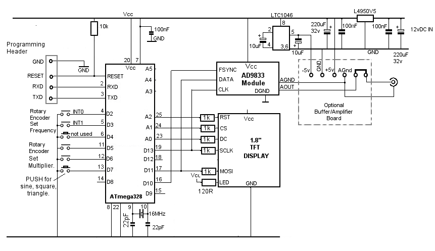
AD9833 Waveform Module vwlowen.co.uk
*/

#include <SPI.h>
#include <Rotary.h> // Rotary encoder: https://github.com/brianlow/Rotary


#define dc A0 // Define pins for TFT display.
#define cs A1 //
#define rst A2

#include <Adafruit_GFX.h> // Core graphics library

// include Adafruit library OR QDTech library depending on the display's controller chip.

// #include <Adafruit_ST7735.h> // Hardware-specific library
// Adafruit_ST7735 tft = Adafruit_ST7735(cs, dc, rst);

#include <Adafruit_QDTech.h> // Hardware-specific library
Adafruit_QDTech tft = Adafruit_QDTech(cs, dc, rst);


// https://github.com/zigwart/Adafruit_QDTech


#define BLACK 0x000 // Define the display colours we'll be using
#define BLUE 0x001F // so they're constants regardless of which
#define GREEN 0x07E0 // display library we use.
#define YELLOW 0xFFE0
#define GREY 0x632C

const int SINE = 0x2000; // Define AD9833's waveform register value.
const int SQUARE = 0x2028; // When we update the frequency, we need to
const int TRIANGLE = 0x2002; // define the waveform when we end writing.

int wave = 0;
int waveType = SINE;
int wavePin = 7;

int freqUpPin = 2; // Define rotary encoder pins.
int freqDownPin = 3;
int stepUpPin = 5;
int stepDownPin = 6;

const float refFreq = 25000000.0; // On-board crystal reference frequency

const int FSYNC = 10; // Standard SPI pins for the AD9833 waveform generator.
const int CLK = 13; // CLK and DATA pins are shared with the TFT display.
const int DATA = 11;

Rotary r = Rotary(freqUpPin, freqDownPin); // Rotary encoder for frequency connects to interrupt pins
Rotary i = Rotary(stepUpPin, stepDownPin); // Rotart encoder for setting increment.

unsigned long freq = 1000; // Set initial frequency.
unsigned long freqOld = freq;

unsigned long incr = 1;
unsigned long oldIncr = 1;

void setup() {

pinMode(freqUpPin, INPUT_PULLUP); // Set pins for rotary encoders as INPUTS and enable
pinMode(freqDownPin, INPUT_PULLUP); // internal pullup resistors.
pinMode(stepUpPin, INPUT_PULLUP);
pinMode(stepDownPin, INPUT_PULLUP);
pinMode(wavePin, INPUT_PULLUP);

// Can't set SPI MODE here because the display and the AD9833 use different MODES.
SPI.begin();
delay(50);

// Initialize either Adafruit OR QDTech display
//QDTech display
tft.init();

//Adafruit display
// tft.initR(INITR_BLACKTAB); // initialize a ST7735S chip, black tab

tft.setRotation(3);
tft.setTextWrap(false); // Allow text to run off right edge

tft.fillScreen(BLACK);
tft.drawFastVLine(20, tft.height()-55, 4, GREY); // Display 'static' cosmetic text.
tft.drawFastVLine(40, tft.height()-55, 4, GREY);
tft.drawFastVLine(47, tft.height()-55, 4, GREY);
tft.drawFastVLine(88, tft.height()-55, 4, GREY);
tft.drawFastVLine(95, tft.height()-55, 4, GREY);
tft.drawFastVLine(134, tft.height()-55, 4, GREY);

tft.drawFastHLine(20, tft.height()-52, 20, GREY);
tft.drawFastHLine(47, tft.height()-52, 42, GREY);
tft.drawFastHLine(95, tft.height()-52, 40, GREY);

tft.setTextColor(GREY);
tft.setCursor(23, tft.height()-48);
tft.print("MHz kHz Hz");

tft.setCursor(15, tft.height() -20);
tft.setTextSize(1);
tft.drawFastHLine(0, tft.height() - 23, tft.width()-10, BLUE);
tft.setTextColor(BLUE);
tft.println("AD9850 10 Hz to 5 MHz ");
tft.print(" waveform generator");


// Configure interrupt for rotary encoder and enable.
PCICR |= (1 << PCIE2);
PCMSK2 |= (1 << PCINT18) | (1 << PCINT19);
sei();

AD9833reset(); // Reset AD9833 module after power-up.
delay(50);
AD9833setFrequency(freq, SINE); // Set the frequency and Sine Wave output
updateDisplay();
}

void updateDisplay() {

// To complicate things, the display uses SPI MODE0 but the AD9833 uses SPI MODE3 so it's
// necessary to switch modes before each SPI transfer.
SPI.setDataMode(SPI_MODE0);

tft.fillRect(50, 10, 100, 12, BLACK); // Clear text.

tft.setTextColor(YELLOW);
tft.setCursor(55, 10);
tft.setTextSize(1);
switch (waveType) {
case SINE: tft.print(" sine"); break;
case SQUARE: tft.print(" square"); break;
case TRIANGLE: tft.print("triangle"); break;
}

tft.fillRect(25, 50, 140, 14, BLACK); // Clear frequency numerals.
tft.setTextColor(GREEN);
tft.setTextSize(2);
tft.setCursor(25, 50);
format(freq); // Show frequency in formatted form.

}

void format(unsigned long value) {

// Break the frequency value down into individual digits & into variable 'digit'.
// If a digit corresponds with the currently-selected x10 increment, change the
// text colour to YELLOW. All other digits and commas are GREEN.

unsigned long j = 1000000;

for (int i=6; i>=0; i--) {
int digit = (value / j) % 10;
incr == j ? tft.setTextColor(YELLOW): tft.setTextColor(GREEN);
tft.print(digit);
if ((i == 6) || (i == 3)) { // Add commas at millions and thousands
tft.setTextColor(GREEN);
tft.print(",");
}
j /= 10;
}
}


void loop() {

if (oldIncr != incr) {
updateDisplay();
oldIncr= incr;
}

// Check 'increment' rotary encoder. Increase or decrease 'increment' by a factor of x10
// if encoder has been turned.
unsigned char result = i.process();
if (result) {
if (result == DIR_CW) {if (incr < 1000000) incr *= 10;}
if (result == DIR_CCW) {if (incr >= 10) incr /= 10;}
updateDisplay();
}

// Check if push button on 'increment' rotary encoder is pushed and set Wave Type accordingly.
if (digitalRead(wavePin) == LOW) {
wave += 1;
if (wave > 2) wave = 0;
switch (wave) {
case 0: waveType = SINE; break;
case 1: waveType = SQUARE; break;
case 2: waveType= TRIANGLE; break;
}
AD9833setFrequency(freq, waveType); // Set AD9833 to frequency and selected wave type.
updateDisplay();
delay(200);
}

if (freq != freqOld) { // If frequency has changed, interrupt rotary encoder
AD9833setFrequency(freq, waveType); // must have been turned so update AD9833 and display.
updateDisplay();
freqOld = freq; // Remember new frequency to avoid unwanted display
} // and AD9833 updates.
}

// AD9833 documentation advises a 'Reset' on first applying power.
void AD9833reset() {
WriteRegister(0x100); // Write '1' to AD9833 Control register bit D8.
delay(10);
}

// Set the frequency and waveform registers in the AD9833.
void AD9833setFrequency(long frequency, int Waveform) {

long FreqWord = (frequency * pow(2, 28)) / refFreq;

int MSB = (int)((FreqWord & 0xFFFC000) >> 14); //Only lower 14 bits are used for data
int LSB = (int)(FreqWord & 0x3FFF);

//Set control bits 15 ande 14 to 0 and 1, respectively, for frequency register 0
LSB |= 0x4000;
MSB |= 0x4000;

WriteRegister(0x2100);
WriteRegister(LSB); // Write lower 16 bits to AD9833 registers
WriteRegister(MSB); // Write upper 16 bits to AD9833 registers.
WriteRegister(0xC000); // Phase register
WriteRegister(Waveform); // Exit & Reset to SINE, SQUARE or TRIANGLE

}

void WriteRegister(int dat) {

// Display and AD9833 use different SPI MODES so it has to be set for the AD9833 here.
SPI.setDataMode(SPI_MODE2);

digitalWrite(FSYNC, LOW); // Set FSYNC low before writing to AD9833 registers
delayMicroseconds(10); // Give AD9833 time to get ready to receive data.

SPI.transfer(highByte(dat)); // Each AD9833 register is 32 bits wide and each 16
SPI.transfer(lowByte(dat)); // bits has to be transferred as 2 x 8-bit bytes.

digitalWrite(FSYNC, HIGH); //Write done. Set FSYNC high
}


// Interrupt service routine for the 'frequency' rotary encoder.

ISR(PCINT2_vect) {

unsigned char result = r.process();
if (result) {
if (result == DIR_CW) { // Clockwise rotation so add increment to frequency
if ((freq + incr) < 6000000) freq+=incr;

} else {
if (freq > incr) { // Counter-clockwise rotation so subtract increment
freq -= incr; // from frequency unless it would result in a negative
} else { // number.
if (freq >= 1) incr /= 10;
if (incr < 1) incr = 1; // Compensate for math rounding error.
}
}
}
}

AD9833-waveform-generator-circuit.png


AN-1070 APPLICATION NOTE на AD9833
http://www.analog.com/media/en/technical-documentation/application-notes/AN-1070.pdf

Русский даташит на AD9833
http://microsin.net/adminstuff/hardware/ad9833-programmable-waveform-generator.html

---------- Сообщение добавлено в 11:54 ---------- Предыдущее сообщение размещено в 11:44 ----------

На всякий случай...
'Note: Changed to manually select DDS chip, write 6 bytes, then manually
'deassert DDS chip, around all 6 bytes, not around 2 byte words.
'
'Freq is >10000 and <= 12.5 MHz
'Calculate the Freq Register using Double precision
'On Entry have FD3 = FM = 10.73741824
'Generate an 8 byte, (64 bit), value for the value to be further
'formatted to put in the frequency register.
'First Send Control Word, above.
'Then send two bytes: 01 and 14 LSBs of data
'Then send two bytes: 01 and 14 MSBs of data
'Example:
'12.5 MHZ (the Highest Freq in range for this chip and project:
'12.5MHz = 12500000 Hz
'12500000 * 10.7374184 = 134,217,730 This is the 28 bit data for the freq register
'134,217,730 = 1000 0000 0000 0000 0000 0000 0010 (28 bits)
'Now format it for loading into the chip, 2 writes of 2 bytes each
'Send 01 and 14 LSB: 0100 0000 0000 0010
'Then 01 and 14 MSB: 0110 0000 0000 0000

'DDS MUST have the Clk HIGH when CS\ goes low.
'Can set this up in Bascom ConfigSPI
'The DDS chip clocks in the data on the Falling Edge of the Clk.
'The DDS chips wants data MSB First.


---------- Сообщение добавлено в 11:57 ---------- Предыдущее сообщение размещено в 11:54 ----------

Не работающий код
Таблица 9. Запись 0xFFFC000 в регистр FREQ0.

Данные SDATA Результат ввода слова
0010 0000 0000 0000 Запись слова управления: (D15, D14) = 00, B28 (D13) = 1, HLB (D12) = X
0100 0000 0000 0000 Запись регистра FREQ0: (D15, D14) = 01, 14 бит LSB = 0x0000
0111 1111 1111 1111 Запись регистра FREQ0: (D15, D14) = 01, 14 бит MSB = 0x3FFF

config PORTD.4=output
config PORTD.5=output
config PORTD.6=output

Dim Tm As Word

Tm=&B0000 0000 0001 0000 0000 ' Сброс регистров, RESET без пробелов записано !!!
gosub AD9834

Tm=&B0000 0000 0000 0000 0000 ' Сброс RESET
gosub AD9834

Tm=&B0010 0000 0000 0000 0000 ' настройка
gosub AD9834

Tm=&B0100 0000 0000 0000 ' запись старших битов
gosub AD9834

Tm=&B0111 1111 1111 1111 ' запись младших битов, разное записывал сюда...
gosub AD9834


AD9834:
Reset Portd.6
Shiftout Portd.5 , Portd.4 , Tm , 0
Set Portd.6
Return

почти одно и тоже AD9834:
Код:

'-----------------------------------------------

Dim Tmpw As Word '16-разр. временный регистр
Dim Wadr As Word '16-разр. временный регистр
Dim Tmpl As Long 'временные данные
Dim R_f As Single 'текущее значение частоты Герцах
Dim Ua As Single 'временное значение


' Определение констант
Const Dds_osc = 20000000 'тактовая частота DDS частотного модулятора
Const Mulf1 = 4 * 268435456 / Dds_osc 'коэффициент преобразования в частотное число синтезатора

' _________________ 0 (адрес)
' | ________________ 0 (адрес)
' || _______________ B28 0 - два 14 бит.рег, 1 - две послед оп. записи
' ||| ______________ HLB 0 - LSB, 1 - MSB при B28 = 1, при B28 = 0 не действ.
' |||| _____________ FSEL
' ||||| ____________ PSEL
' |||||| ___________ PIN/SW 0 - SoftWare, 1 - Pin
' ||||||| __________ Reset 0 - нет, 1 - да
' |||||||| _________ Sleep1 0 - MCLK, 1 - откл
' ||||||||| ________ Sleep12 0 - activ, 1 - powerdown
' |||||||||| _______ OPBITEN 0 - SBO off, 1 - SBO on)
 

Похожие темы

Сверху